Rationale
![]() Most hackers are driven by the quest for elegance. To create something of beauty, maybe useful, simple in nature and yet high in impact.
Beyond elegance, we seek (visual) appeal, low costs and a high degree of repeatability for a large audience.
Most hackers are driven by the quest for elegance. To create something of beauty, maybe useful, simple in nature and yet high in impact.
Beyond elegance, we seek (visual) appeal, low costs and a high degree of repeatability for a large audience.
PixelTime is my attempt at creating something elegant. It is useful (I also call it the “how to dress the kid’s device”), it is very easy to make (no soldering required), looks fantastic, is very repeatable (little manual labour required), costs about 40 EUR and takes about 30 minutes to assemble (+ optional case).
Display
Choosing the right display for a project is increasingly difficult these days - there are just too many options! E-Paper, COG LCD, TFT, scanning laser, POV, glow-in-the-dark paper, WS2812B matrix, ferrofluid – you name it. Also, the choice of display defines to some extend the system that drives it. High resolution color varieties require high bus speeds, more memory and processing power. This is less of a problem cost-wise (5 EUR Raspberry PI Zero - check), however, then we usually add the extra complexity of a full blown Linux distribution. This will reduce simplicity and repeatability significantly whilst increasing the involved (set-up) time effort. In the interest of simplicity I settled on a ESP8266 based NodeMCU micro controller that comes with pre-soldered pin headers. On the display side of things, I chose a Chinese P10 RGB led matrix module that integrates all the necessary driver electronics into a single piece of kit. It offers 32x16=512 RGB pixels with a 1cm spacing for as little as 17 EUR. The equivalent with WS2812B leds would cost at least twice as much. Furthermore, the P10 module comes fully assembled in a sturdy plastic module frame with defined screw mounts and offers connectivity via two standard pin-headers. Unfortunately, since no reasonable Arduino driver for the ESP8266 existed, I had to write my own. The P10_matrix driver is based on a neat little hack that reduces the number of required GPIOs far enough, so it can be driven by the ESP8266. Since it is also Arduino GFX compatible, you can use all the standard graphics primitives and fonts.
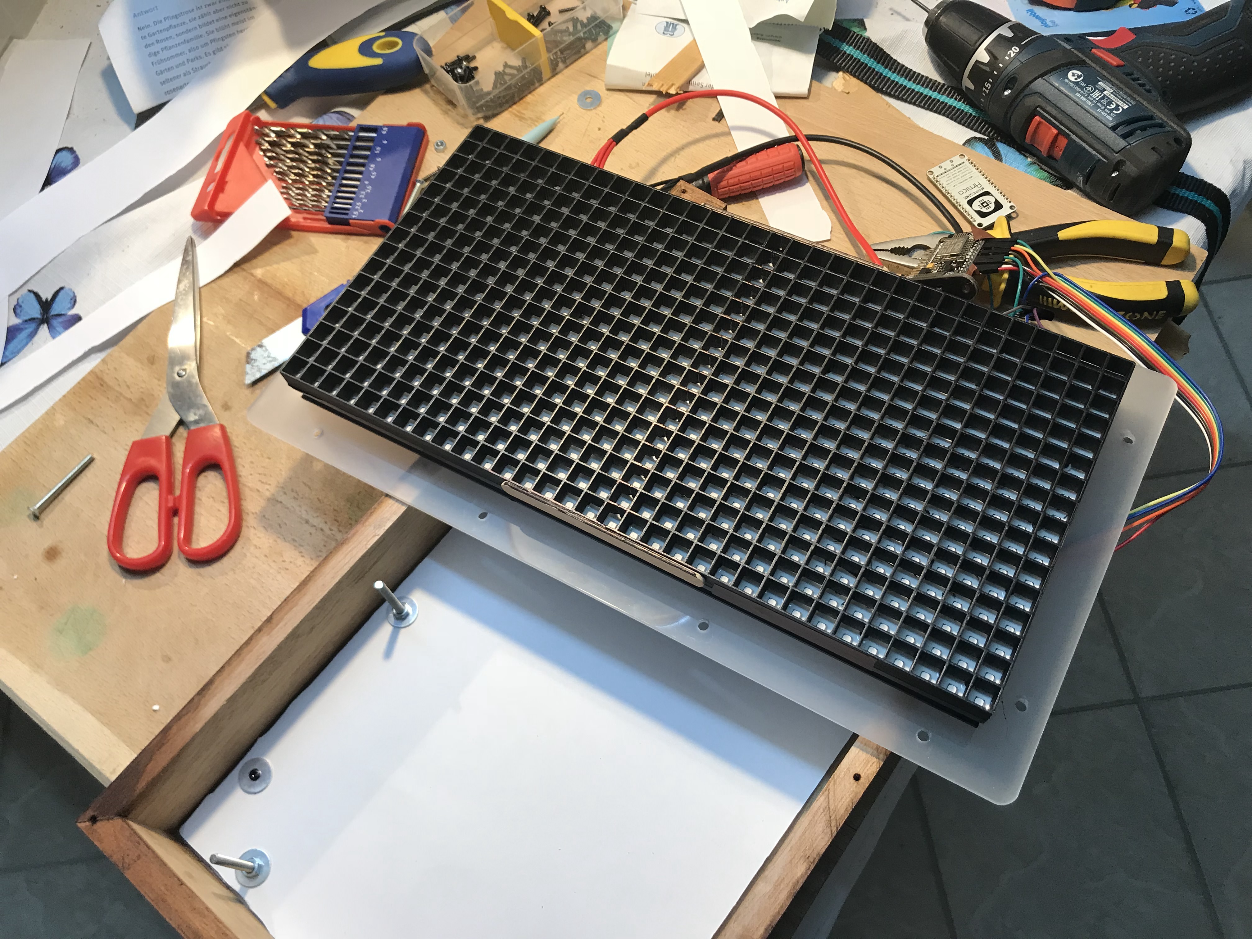
The link also includes the information on how to connect the NodeMCU to the LED matrix. The picture below depicts the library in the early stages of development.
In the interest of simplicity I settled on a ESP8266 based NodeMCU micro controller that comes with pre-soldered pin headers. On the display side of things, I chose a Chinese P10 RGB led matrix module that integrates all the necessary driver electronics into a single piece of kit. It offers 32x16=512 RGB pixels with a 1cm spacing for as little as 17 EUR. The equivalent with WS2812B leds would cost at least twice as much. Furthermore, the P10 module comes fully assembled in a sturdy plastic module frame with defined screw mounts and offers connectivity via two standard pin-headers. Unfortunately, since no reasonable Arduino driver for the ESP8266 existed, I had to write my own. The P10_matrix driver is based on a neat little hack that reduces the number of required GPIOs far enough, so it can be driven by the ESP8266. Since it is also Arduino GFX compatible, you can use all the standard graphics primitives and fonts.
The link also includes the information on how to connect the NodeMCU to the LED matrix. The picture below depicts the library in the early stages of development.

Parts and assembly
Many big-pixel LED matrix builds use hand-made cardboard or plywood separator grids. Fortunately, the P10 matrix is small enough that the separator grid can be 3D printed. So I created a 16x16 separator grid model, 3D printed it twice and glued the pieces together to form one big 32x16 grid. To obtain evenly lit pixels, I used a sheet of A3 copy paper as a diffuser screen. As the front “glass” I got a piece of 3mm black/transparent acrylic. For the back-plate, I screwed another piece of acrylic to the back of the matrix module using the standard screw mounts. The combination of all these parts now leads to something rather neat: all electrical connections are made using standard Dupont style jumper cables. The module frame, the separator grid and the paper are simply sandwiched between the two pieces of acrylic using a few longish M3 screws.
 If you have access to a laser cutter for the acrylics and prefer a clean techie look, you might just stop here. In my case, I chose to make a wooden case for the clock. I had an old slatted bed-frame lying around that wanted to be used. So after some woodwork and a few layers of mahogany oil I had a nice box that neatly fits next to my radio.
 To supply and program PixelTime, I also created a simple NodeMCU panel mount. This mount exposes the micro USB connector as well as both click buttons to the outside of the box. A 2A phone charger and a nice 2m USB cable from ebay completes the assembly.

Software
For the software to run you will need to open an account with openweathermap (it's free), edit the Wifi network credentials and update the REST request strings with your openweathermap API key and location. For time synchronization I used this ESP8266 NTP library which is based on the one from GMAG11 with added hour, minute and second functions. Apart from that, you should just be able to flash the NodeMCU with the code as is. Flashing the NodeMCU requires Arduino and the ESP8266 Arduino core.The display currently shows the temperature/weather of the current and next day. It jumps between minimum temperatures/worst weather and maximum temperatures/best weather in a 5 second interval. The dot on the bottom left indicates what the display is currently showing. I created some low resolution animated weather icons that are more or less compatible with the openweathermap rest API response. I didn't bother drawing all the night icons (who cares - it's dark).
![]() Congratulations ... you made it all the way through. Enjoy your PixelTime!
Congratulations ... you made it all the way through. Enjoy your PixelTime!
![]()
Bill of materials
Prices include delivery
- P10 LED Matrix (Aliexpress) – 17 EUR
- Dupond jumper cables (Aliexpress) – 0.5 EUR
- NodeMCU ESP8266 – 3 EUR
- Acrylics – 10 EUR
- 3D prints – 3 EUR (plastics)
- 2A USB charger and 2m cable (ebay) – 8 EUR
- M3x50mm screws and nuts – 2 EUR
- Box – Free
- TOTAL: 43 EUR