The excuse
 My wife wanted to have a new radio for the kitchen and threatened to buy some ~100 EUR CD/analog radio combo if I don't do anything about it. So I committed myself to come up with something 'infinitely better' for the same amount. How wrong I was to believe that one could simply buy a nice and easy to use web-radio that can play music from our NAS as well as tolerates the occasional ratatouille covered finger.
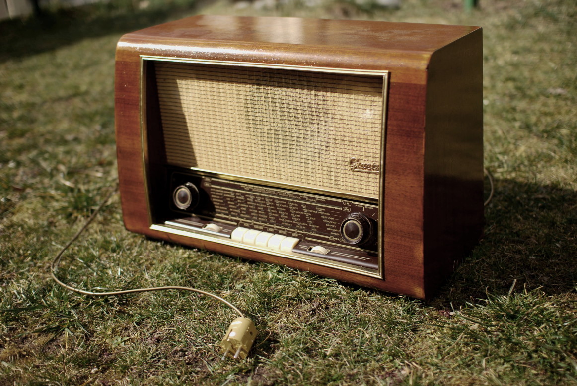
So I set out to build a web-radio on the basis of an old, non-functional radio I once bought on a flea market. It is a German Greatz vacuum tube radio built between 1953 and 1954. On closer inspection, I found that some of the tubes as well as some of the circuitry was missing (no idea what the previous owner did to the poor thing). Looking at the picture below, I still like the worn look of it. However, for it to be tolerated in the kitchen, I had to bring it up to scratch. This process involved refurbishing the outside, the installation of a new amp & speakers, a network capable audio player as well as some analog / digital conversion to make use of all those nice dials and buttons.
Features:
- Indestructible solid wood construction
- Makes awesome CLOCK! sound when pressing a selector switch button
- Super non-linear analog dials (it is not logarithmic, what is it?)
- Pressure sensitive optical push button (TM)
- Most important part is a 90s computer mouse
- Takes roughly 1 minute to warm up
- Plays happy kids songs with the press of a button
- Has SSH access
- Natural noise floor for believable FM radio reproduction
- Can be licked
The sources and full-res pictures can be found in the zip/tar file or here here.
The shell
 I started off by removing the brass strips that frame the speaker compartment. I also removed all remaining electrical parts of the original radio from the inside. The next step was to carefully remove the varnish with fine sand paper. I now had a very nice wooden radio shell which I chose to stain in a dark brown color.
After some consideration I settled on shellac for the coating. I read quite a bit about how to do this (takes a lot of practice and time if you want to get it right and if you are aiming for an absolutely smooth piano-like surface). Given the fact that my wife was starting to check out kitchen radios on Amazon, I went for the relatively easy to do mate finish option. To do this, you simply apply a fine layer of shellac with a paint brush, let it dry for 12ish hours and sand it down with very fine sand paper. Repeat the process 4-5 times. The shellac leaves have to be dissolved in pure ethanol alcohol for 24h before use. Only use very small amounts of shellac for each coating. Otherwise you will end up having a bumpy surface that you have to sand down later (pain). The result is acceptable, however, far from a piano like surface which you could achieve with more time and patience. Another advantage of using shellac is that it is a natural product and certified as a coating for kids toys.
I started off by removing the brass strips that frame the speaker compartment. I also removed all remaining electrical parts of the original radio from the inside. The next step was to carefully remove the varnish with fine sand paper. I now had a very nice wooden radio shell which I chose to stain in a dark brown color.
After some consideration I settled on shellac for the coating. I read quite a bit about how to do this (takes a lot of practice and time if you want to get it right and if you are aiming for an absolutely smooth piano-like surface). Given the fact that my wife was starting to check out kitchen radios on Amazon, I went for the relatively easy to do mate finish option. To do this, you simply apply a fine layer of shellac with a paint brush, let it dry for 12ish hours and sand it down with very fine sand paper. Repeat the process 4-5 times. The shellac leaves have to be dissolved in pure ethanol alcohol for 24h before use. Only use very small amounts of shellac for each coating. Otherwise you will end up having a bumpy surface that you have to sand down later (pain). The result is acceptable, however, far from a piano like surface which you could achieve with more time and patience. Another advantage of using shellac is that it is a natural product and certified as a coating for kids toys.
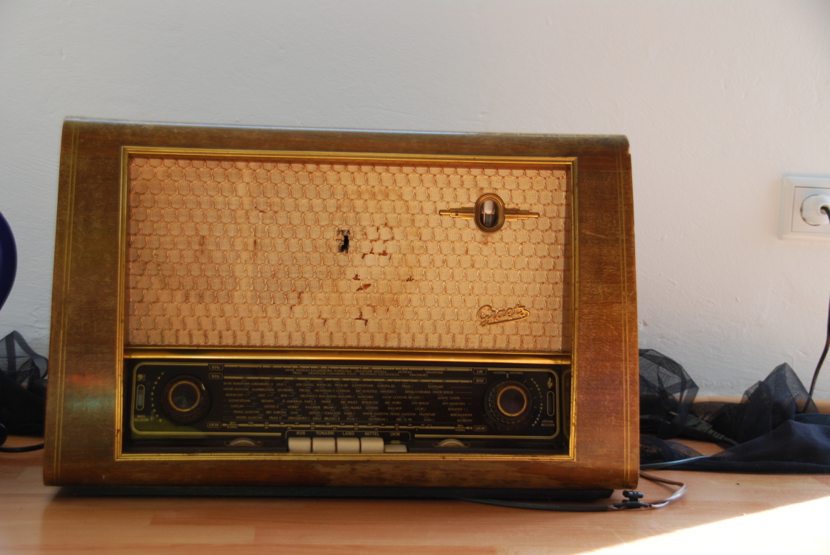
Repairing the front fabric was trickier than I thought. My wife tried to find a similar fabric to the original one but no avail. There is an old lady in Holland that will hand weave any radio fabric you like, but that is a bit too pricey. I finally settled on a Fender Wheat guitar amp 'grill cloth' - not as nice as the original, but at least the kids will have a hard time poking holes in it. I also replaced the MDF-board that held the original speaker in place and glued the new 'grill cloth' to it with transparent wood glue.
Finally, I thoroughly cleaned all the buttons and dials with a mild soap mixture. Before gluing the brass strips back on, I cleaned them with a salt and vinegar mixture. Unfortunately, these strips only have a very fine layer of brass that is severely damaged. Although I managed to remove most of the stains, it only made the damages in the surface more visible. I may replace these strips one day if I have the right tools to cut them properly.
The amp & speakers
I would have loved to use a small tube amp for this project but I could not find anything that sounds acceptable and fits within the budget. Instead, I went down the chip amp route. I own a Logitech X 230 / sub-woofer combo, which sound amazing for the price, but it did not physically fit the case. So I downsized a bit and settled on a pair of Logitech X-140 PC speakers in the hope they would sound equally nice. Unfortunately they did not. Upon removing the drivers and the amp from the plastic computer speakers, I discovered that there is only one active driver per speaker although the speaker superficially looks like it has two. The second speaker turned out to be a passive membrane pictured below.
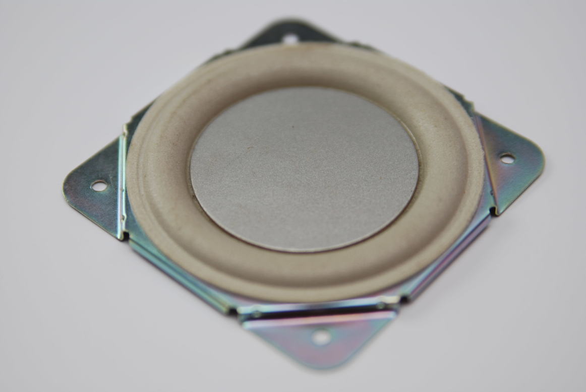 I want to make myself believe that Logitech's clever loudspeaker design & passive membrane (they call it a 'pressure driver') results in a superb low frequency response but instead, I feel a bit ripped off. I mounted the two little drivers on a new MDF board, screwed the board into the radio and tested the setup with an mp3 player - no bass to speak of :(
Fortunately, I discovered that the guy who tortured the poor tube radio to death also replaced the stock speaker with a rather modern Visaton wide band speaker. A match made in heaven. I simply soldered the wide band speaker in parallel to one of the small Logitech speakers (... it surely can drive 2Ohms) and moved it a bit off center to preserve the stereo effect. The sound is pretty good now. Lesson learned: invest more in audio hardware - I think 20 Euros more would have made a big difference.
Another problem I encountered was a lot of noise and humming. This was most likely noise being picked up from one of the switched mode power supplies operating in close proximity to the amp (Logitech actually circumvents this problem by placing the power supply in one loudspeaker and the amp in the other). To get around this problem, I went to the supermarket and got a tin box (yummy chocolates) that could house the amp and act as a shield - this completely solved the noise issue. I also screwed the amp's heat sink to the lid of the tin so it would not overheat. In practice the amp does not even get hand warm now.
Network audio player
My fist idea of implementing the player was using a spare Edimax 6200n wifi router with OpenWRT that mounts our NAS via Samba, runs the MPD server and plays audio via a USB soundcard. This did not work out so well for several reasons. First of all, current trunk versions of OpenWRT for the 6200n have broken network functionality which essentially leaves the router inaccessible from the outside. After some reading of bug reports and patching the sources, I managed to compile a working image. The next problem was that I was unable to get two USB devices (USB sound dongle & Arduino) in conjunction with a USB hub to work. This may be an inherent limitation of the SoC that only one USB device is supported at a time.
So I took the plunge and soldered a serial cable to the PCB of the Edimax router and connected the Arduino (see next section) the old fashioned way. That left me with only one usb device (audio) which worked reasonably well. What finally killed the router idea was the severe flash memory limitation of 4MB. I was unable to fit Openwrt with USB-audio support, MPD and Samba file system modules within that space. It is probably possibly, but I was pretty fed up at that point. I briefly experimented with network mounted root but then gave up (root on a USB stick did not work either since I would have had to use a hub again).
So instead I chose a Raspberry PI model A for the network audio player. I chose model A over model B since it is cheaper and I only need one usb port (wifi); serial and audio are on board. So the setup now involved the PI, a 4GB class 10 SD-Card, an Edimax EW-7811UN wifi dongle and a phone charger as the power supply. In the beginning I used Arch Linux, since I was intrigued by the promise of short boot times. Unfortunately, I had to spend a lot of time to get used to their systemd service manager. What killed Arch for me in the end was the buggy serial kernel driver in the stock arch distro for Raspberry PI. I experienced data loss and random serial device lockups. I did not investigate this issue any further since I finally wanted things to work. After changing to Raspbian, the same code, that kept me cursing for days, worked flawlessly.
Interfacing the controls
I wanted to preserve the feeling of the radio as much as I can hence all of the original functionality would have to be re-implemented. This involved reading analog values from all potentiometers (volume, bass, treble), reading the state of the selector switches as well as reading the station selector dial. All this is performed by an Arduino that does some additional filtering and is connected to the Raspberry PI via the serial interface. Interfacing the potentiometers was fairly standard. I connected the ends to GND and +5V and the wiper pins to 3 analog inputs of the Arduino. I also read the state of the switches via an analog input in order to save IO pins. This is conducted by connecting resistors of different values to the switches and measuring the voltage drop over an additional resistor. Although the Arduino has a 10bit analog digital converter, the actually usable resolution is more like 6bits.
This is due to two reasons: for one, potentiometers are a bit noisy anyway and neither the potentiometers nor my cabling is shielded. This is less problematic and can easily be filtered with some averaging code. What really reduced the resolution drastically was the old school construction of the spring loaded selector switch. On pressing one of the buttons, you will hear a massive 'clack!' that rattles the whole radio and is physically moving the potentiometers. I takes up to a second for all the values to stop dancing about. In the end, I scaled the value range of the potentiometers to 0-100 which is the default format for MPD and Alsa volume settings.
Reading the station selector dial was a whole different story. I played with the idea of feeding some AC current into the variable capacitor that was connected to the selector dial via a system of pulleys. The capacitance could then, in theory, be inferred from the voltage drop over the capacitor. The disadvantage of this approach was the limited range of the selector dial: it would have a natural 'end' where the capacitor is either fully open or fully closed. This concept is somewhat incompatible with a playlist of arbitrary length. So I had to come up with another solution that implemented an 'endless' selector dial.
My first approach was to reuse the original pulley system and to replace the capacitor with an analog ball mouse connected to the Arduino thanks to the superb Arduino PS/2 library.
 This worked reasonably well, however, I ran into a very practical problem: how does one produce an endless cord loop without tying a knot? My knot just would not go around the tiny spindle of the PS/2 mouse. I know the principle of splicing from my sailing lessons; however this cord is like 0.5mm thick! Instead of investigating the art of invisible knots any further, I opted for a different solution.
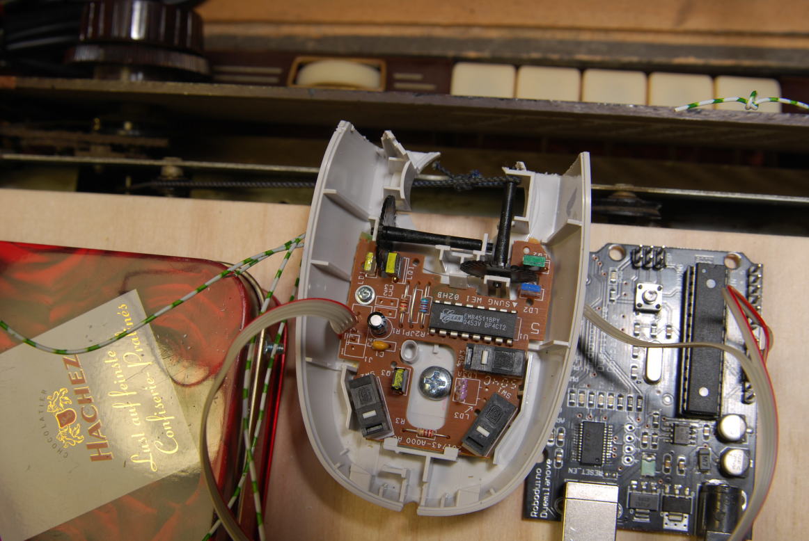
The shaft of the station selector dial connects to a metal cast disk located in the base of the radio. I can only presume that this disk is intended to give the dial some additional inertia in order make it feel premium. Metal inertia disk! How awesome. One has to feel sorry for product designers these days. This disk gave me an idea. Maybe the disk was wide enough so I could use an optical mouse to pick up the disk's movement. This would bypass the knot issue altogether. Luckily, I found an old optical PS/2 mouse in my stash. I cut the mouse case down until I only had the base with PCB, optical sensor and optics left. I then attached a piece of sheet metal to both, the radio's chassis and the mouse, and positioned the sensor over the disk so it was aligned with the sensors x-axis.
This worked reasonably well, however, I ran into a very practical problem: how does one produce an endless cord loop without tying a knot? My knot just would not go around the tiny spindle of the PS/2 mouse. I know the principle of splicing from my sailing lessons; however this cord is like 0.5mm thick! Instead of investigating the art of invisible knots any further, I opted for a different solution.
The shaft of the station selector dial connects to a metal cast disk located in the base of the radio. I can only presume that this disk is intended to give the dial some additional inertia in order make it feel premium. Metal inertia disk! How awesome. One has to feel sorry for product designers these days. This disk gave me an idea. Maybe the disk was wide enough so I could use an optical mouse to pick up the disk's movement. This would bypass the knot issue altogether. Luckily, I found an old optical PS/2 mouse in my stash. I cut the mouse case down until I only had the base with PCB, optical sensor and optics left. I then attached a piece of sheet metal to both, the radio's chassis and the mouse, and positioned the sensor over the disk so it was aligned with the sensors x-axis.
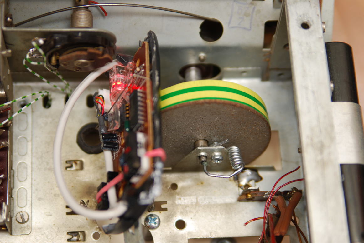 Since I could simply reuse my code from the ball mouse experiment, I had a working digital selector dial within moments. After some happy endless station dialing I asked myself what else I could use the mouse for. It had a few switches and another optical sensor axis left unused. The y-axis of the mouse sensor would correspond to moving the selector dial in and out which would be a .... push button! So all I had to do was to introduce some y-axis wiggle into the selector dial. This was easily done by cutting some spacers to size that held the shaft in place. I also drilled a small hole in the end of the shaft and attached a peg spring so it would bounce back. A few extra lines of code and I had a pressure sensitive optical push button (TM)! Probably the most unusual thing that ever came out of a retro radio build. I later noticed that the uneven silver surface of the disk confused the optical mouse sensor from time to time. I rectified this by putting some electrical tape around it. Now, if there is a change in any value, the analog values together with the digital values from the mouse are pushed to the Raspberry PI via the serial interface. This completes the interfacing part.
I am also toying with the idea of reimplementing the station indicator using a small stepper motor, but I am not missing it yet.
Putting it all together
Now I had an amp, speakers and a serial interface that would inform me about user input. So I connected the serial interface of the Arduino to the correct serial GPIO pins on the Rapsberry PI. A voltage devider performs the 5V to 3.3V level conversion. I also chose to power the Arduino off the PI's 5V/GND GPIO pins.
On the Raspberry PI I now installed the MPD and mounted my NAS via Smaba/CIFS. I then wrote a Python script (actually my first attempt at Python) that does the following. On startup, the script connects to the MPD via the python-mpd library. This took a bit more effort than I thought since the MPD likes to drop the connection rather frequently - some reconnection code did the trick.
The script then starts to liste on the serial interface and reacts to any value changes: Volume is set via python-mpd, selector switches select several pre-defined playlist and base / treble is set via an alsa mixer shell command. In my case VHF/UKW is web radio and MW is kid's songs, etc. I later disabled the base / treble because it annoyed me. For the kids songs I simply execute a next/previous command every time the station selector is turned a pre-defined amount. My pressure sensitive optical push button (TM) is currently used as a pause/play button, but may serve a different purpose in the future.
 For playing web-radio, however, I took a somewhat different approach than to execute simple next/previous commands. Maybe I am a bit sentimental, but I really like the haptics of analog radios. One does not simply push a button and the next, perfectly tuned station pops up, but one has to actually interact with the radio. This little feeling of accomplishment if one manages to tune into a very weak station is just something that got lost with the introduction of digital push buttons.
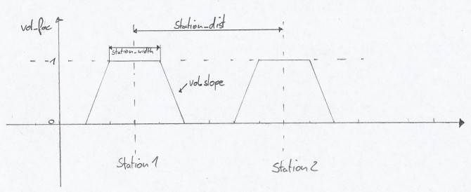
Fortunately, this feeling can be brought back using software. What the volume code does is pictured above: it reduces the volume if the station selector dial is not perfectly 'tuned' to an imaginary station. I also considered adding a noise floor between stations but I did not have to. The Raspberry PI audio driver is known to have a few bugs (e.g. the plop issue). Another problem seems to be, that if the volume is reduced to 0, the PI is still sending a faint, distorted signal to the audio interface. My amp picks up on this and produces something that sounds a bit like static - perfect. Another advantage of having a dead-zone of zero volume or static between web radio stations is that the buffering delay is not noticeable; it appears like the stations are just all there.
For playing web-radio, however, I took a somewhat different approach than to execute simple next/previous commands. Maybe I am a bit sentimental, but I really like the haptics of analog radios. One does not simply push a button and the next, perfectly tuned station pops up, but one has to actually interact with the radio. This little feeling of accomplishment if one manages to tune into a very weak station is just something that got lost with the introduction of digital push buttons.
Fortunately, this feeling can be brought back using software. What the volume code does is pictured above: it reduces the volume if the station selector dial is not perfectly 'tuned' to an imaginary station. I also considered adding a noise floor between stations but I did not have to. The Raspberry PI audio driver is known to have a few bugs (e.g. the plop issue). Another problem seems to be, that if the volume is reduced to 0, the PI is still sending a faint, distorted signal to the audio interface. My amp picks up on this and produces something that sounds a bit like static - perfect. Another advantage of having a dead-zone of zero volume or static between web radio stations is that the buffering delay is not noticeable; it appears like the stations are just all there.
The nice thing about this project is that one does not seek perfection but a certain degree of authenticity. For this reason, I don't really mind the 45 seconds boot-up time or the massive PLOP! when you switch it on since it may roughly correspond to the behavior of the original radio.
I sometimes like to not tell visitors about the digital guts of the kitchen radio. Usually, they simply walk up to it and treat it as a very nice old analog radio which they intuitively know how to use - something that won’t happen with a modern digital radio like the Squeezebox. One may argue that the oversimplified interface is crippling the capabilities of the network audio player, which is true, but remember - there are millions of clients for MPD. If one needs the extra complexity of play list management, etc., one can simply connect to the radio via wifi. For that purpose, I installed a MPD client app on our 7" Android tablet that usually serves as a digital cook-book. We haven't used this feature in weeks.
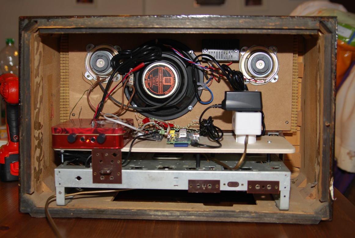 After I finished the functional part, I mounted everything on a plywood board that I cut to size and mounted on the original radio chassis. The base and volume dial of the new amp can now be accessed from the back. There is still some cleaning up to do, like shortening and organizing cables, but this is for later. I also screwed a small multi-plug onto the plywood board that supplies the amp's and the Raspberry PI's PSU. The multi-plug is connected to the original mains switch of the radio that in turn is connected to the power lead. Put the cardboard like rear cover in place and ... all done.
Update 29/11/2015
Over time I added some features and ironed out some bugs. It is rather usable now.
- CD-Player functionality (get one of those and connect it between a laptop CD-drive and the PI's USB connector)
- Added noise tracks between stations (stolen from Sounddog.com). This is realized by running two MPDs at the same time, one for the music, one for the noise tracks, and fading between them.
- Completely rewritten Arduino part. The Arduino now acts as a general purpose serial IO resource. Could be useful for other projects.
- Soft-off feature that keeps the PI powered until the file system is synced and unmounted (get one of those and connect it to the Arduino pin 8 / accross the power switch, respectively).
- Lots of bug fixes
- Boot time roughly one minute
- Turning the station selector too fast confuses the optical mouse -> nothing happens
- Under some conditions, my mobile refuses to connect to the MPD via wifi. This might, however, be due to my crappy wireless router
Bill of materials
Prices include delivery
- Greatz vacuum tube radio - 25 EUR
- Shellac leaves - 8 EUR
- Fender wheat grill cloth - 22 EUR
- MDF board - 1 EUR
- Logitech X-140 PC speakers - 25 EUR
- Hachez chocolates - 5 EUR
- Optical PS/2 mouse - 0 EUR
- Arduino Duemilanove knock-off (Dealextreme) - 11 EUR
- Raspberry PI model A - 32 EUR
- Edimax EW-7811UN Wireless USB Adapter - 11 EUR
- Kingston 4GB class 10 SDHC card - 7 EUR
- 1 amp phone charger - 4 EUR
- TOTAL: 151 EUR